Prototype images courtesy of Moloco Trains
I have an admiration for all things FGE and the consortium of companies which ultimately lead to one of the most successful refrigerator and insulated boxcar fleets in the nation. While FGE is typically regarded as a southeastern, mid-Atlantic corporation based in Alexandria, Virginia, it spread throughout the nation with the addition of CB&Q, Great Northern, National Car Company, and other assets.
During the steel and mechanical era, a FGE car could be seen anywhere throughout the nation which accepted mechanical refrigerators, top iced reefers, or insulated boxcars. These cars roamed far and wide and were often in dedicated service hauling temperature sensitive lading. The utilization of these cars ranged from produce, meat, beer, and just about any commodity imaginable. The obvious appeal is also dictated by the era and area I model, Florida in 1967-1970 which typically saw groceries and inbound beer shipments to the area with outbound produce and orange juice to points north.
One of my favorite models is the Moloco FGE 54'10" FGE built RBL with 10' doors. The kit is no longer in production, however, several Ready to Run models in both Seaboard Air Line Railroad and Atlantic Coast Line Railroad are available directly from Moloco. During the 1967 merger, Seaboard Coast Line inherited 1,599 cars from various series and can be discerned by their first digit of, "4" for former ACL equipment, and, "5" for former SAL equipment. I elected to model SCL 590513 which was constructed in 1963. The prototype was part of the SCL 590500-590058 series of cars rated for 4,595 cubic feet, an interior length of 50'0", Keystone center of car cushioning, and was rated for a nominal capacity of 125,000 pounds (62.5 tons). The prototype also featured a 10'7" door width, and was painted in the typical FGE yellow/oxide brown scheme with "For Greatest Efficiency" lettering.
Below you will find the Seaboard Coast Line 1967 list of combined assets which show the various series and their measurements.
The kit (part number 33001-00) while fully encompassing is quite a puzzle of plastic if you have never constructed one. Additionally, the instructions provided are not specific to the FGE kit, so while constructing my model of SCL 590513, I decided to take some time to address the components utilized for a Keystone cushioning equipped car. The existing Moloco instructions will better serve to orient you to the kit components, however, I hope this will serve as a guide for this wanting to model from the kit. The kit is assembled as a flat kit and having some experience with these kits, I wanted to share my experiences with fellow modelers as there are subtle construction techniques which can save you frustration and time.
The kit consists of a detailed underframe, highly detailed sides, 4/3/R1 improved dreadnaught welded ends, and a Stanray diagonal panel roof with a FGE specific running board and laterals. It also includes Kadee 158 couplers and highly detailed 70-ton ASF roller bearing trucks. The details provided are some of the best available and the only items necessary to complete the kit are paint and decals.
Speaking of decals, those too are covered thanks to Dan Kohlberg's excellent decal sets which cover a full range of FGE cars. There are no finer HO scale decals are available for these kits, so don't waste your time or money with the usual companies as they simply do not compare (Dan Kohlberg FGE Decals are available through the link).
The kit should be opened and inspected for all of the necessary parts which you will quickly see there are extras of nearly all utilized components. The included parts allow the modeler to accurately construct the Keystone or Hydra-Cushion equipped cars. Seaboard Air Line favored the Keystone equipped cars while ACL favored Hydra-Cushion equipped cars.
To begin construction of the kit, you will need basic tools to include a good set of tweezers, a sharp Xacto #11 blade (use and change them often), a Phillips head screw driver, side cutting sprue nippers, a pair of Xuron flush cutting pliers, a pin vise with #79 and #75 drill bits, a small 000 paint brush for applying liquid cement, scrap wire for applying small amounts of adhesive such as CA or Cypox, and a scrap of .030" styrene for application of the side grab irons.
To construct this car, the modeler needs to recognize that it is best practice to assemble it into components for two reasons - paint separation and decals. Not all parts should be applied until after painting and decaling are completed.
While this is a flat kit, it lends itself well to multi-color schemes such as the early FGE scheme. The roof will be silver, the sides will be yellow, the ends, draft gear will be oxide brown, the underframe and trucks will be weathered black. The appropriate paint can be sourced from Tamiya, Mission Models, and Modelflex if desired. I have a collection of Floquil paints that I continue to use, and as such will be utilizing the appropriate colors from my remaining stock.
Bill of Materials:
- Moloco 33001-00 50' FGE RBL Plate B 7+7R, 10 foot centered plug door kit
- Dan Kohlberg FGE SE-22, SE-24 FGEX decal sets
- Tamiya Primer
- Floquil Reefer Yellow or equivalent Chromium yellow
- Floquil Oxide Red or equivalent oxide brown/red
- Tamiya X-18 semi gloss black
- Rustoleum Flat Brown, Camouflage series
- Tamiya XF-20 thinner
- Lacquer Thinner
- Pacer Canopy glue
- Cypox adhesive, Testor's Liquid Cement
Sides:
The Moloco kit is offered with 10' and 12' doors and as such there are two door track widths and two door rod widths to consider. The sides are the most basic component of the kit and require only two parts be applied at this stage of construction. The side grab irons are nested into the corresponding grab iron holes and then cemented into place. Use the .030" styrene spacer to achieve the proper offset from the side and then select and remove the narrow door rod width door tracks.
These are removed using side cutting nippers and are delicate, so take care to not bend or break the tracks as the resulting rebuild is not great fun. Using a small amount of Testor's liquid cement, apply small amounts with a 000 brush into the corresponding holes along the sill and press gently into place.
Roof:
The roof is prepared for assembly and includes the fully accurate Morton running board in place. The modeler will need to examine the overhanging portions of the running board to ensure they are not torqued to one side and will align with the support applied to the end. The corner grab irons and corresponding eyebolts are in place so no installation is necessary. If necessary a small amount of Canopy glue can be applied to the interior supports which run below the roof. This will serve to strengthen any loose joints that are not mechanically bonded.
Ends:
The ends are some of the finest examples of a welded FGE end to date in HO scale. The ends are easily distinguishable due to the number of pre-drilled holes included on the B end. The ends are detailed accordingly using the kit supplied end ladders, cross over platform, cross over grab iron, brake platform, tack boards, uncoupling lever support, brake wheel housing, brake wheel support plate, brake wheel, and running board support.
Begin construction with the A end and drill out the small holes using a #79 drill bit. These include holes for the end grab iron, running board support and cross over platform. The larger holes were drilled using a #75 drill bit to accept the end ladders.
There are multiple variants of tack boards included in the kit, however, there are two sets which include the appropriate mounting pins on the reverse, non-detail side which correspond to the ends. Use a small amount of liquid cement and press the tack board into place. The installation does not require additional drilling, but be sure to dress any of the edges which may contain remnants of molding.
The running board support was installed next using Cypox adhesive. The ladders and running board support are molded in yellow and are made of a slippery type of plastic, as compared to other parts. Removal of the ladders and supports requires care and should be removed with side cutting sprue nippers. A small amount of Cypox was applied with wire and then the cleaned, dressed part was installed. The end grab iron was installed last also using Cypox and adjusted for height prior to the cement setting. The brass cross over platform is pre-bent and was then cemented into place using Cypox. When reviewing prototype photographs, I noted the uncoupling lever support bracket matched the steeper angled version included and removed this part from it's corresponding sprue. The part was cleaned, dressed and cemented into place using liquid cement. Once dry, the end was set aside and construction of the B end was begun.
The build sequence on the B end can be challenging as compared to the A end. The holes were drilled accordingly utilizing #79 and #75 drill bits as with the A end. It is best to install the tack board, the running board support, retainer valve, and brake wheel support bracket first. The included wire (the longest of three short lengths included in the kit) was cemented to the end of the chain linkage of the brake wheel housing utilizing Cypox and allowed to dry. This will be applied later in the construction process of the end. My kit did not include a retainer valve line, so I used a small amount of Tichy phosphor bronze wire to construct this detail. The retainer line was then cut to length and cemented into place. The end grab iron was then installed followed by the cross over platform.

The brake wheel housing (Ajax housing and Universal brake wheel were utilized on the prototype) was removed from the sprue and cleaned. Moloco includes all variants of common brake wheel housings in the kit and four Ajax brake housings. The housing and brake wheel were cemented together utilizing liquid cement. It is important to note that the brake wheel mounting pin will extend beyond the back of the housing and it should not be sanded or removed as it aides in locating this detail part correctly. Using fine tweezers, fish the linkage through the cross over platform and cement the brake wheel housing and wheel into place using liquid cement. The housing should be aligned so that it is straight and vertically aligns with the lower support bracket below the opening in the cross over platform. Once dry, install the appropriate end ladders into place and allow to dry. The remaining brake platform requires bending to shape using smooth jaw pliers. The platform was then cemented into place and the support legs bent inward towards the corresponding NBW detail. The final detail is the uncoupling lever support which was installed similarly on the A end. By constructing in this sequence, it will eliminate the details becoming crowded and interference with alignment.

Set both of the ends aside and notate each end accordingly. As practice, I mark each end with a permanent marker as "A" and "B" on the reverse side so as to eliminate any error during the final construction of the car. The final details to address for the ends are the uncoupling levers which are constructed of etched brass. The below photograph shows the angled extended position of the prototype uncoupling lever support brackets. The etched brass details were bent using smooth jar pliers into shape. These will be applied during final construction, however, they will need to be painted separately.

Underframe:
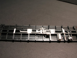
The underframe consists of many varying plastic and wire parts which are seen below. Being a modern insulated boxcar, the prototype is equipped with AB brakes and includes a main reservoir, a brake cylinder, an ABD valve, a bell crank, slack adjuster, hangers, and cushioned draft gear. It is the most daunting portion of the build, so I will simplify it as easily as I can. Please remember, I'm a modeler and not a freight car builder or designer, so many of these terms are based upon that inference and what I can determine based upon my own knowledge.
As with the ends, the underframe is marked as, "A" and "B" to assist in construction of the various components. The U shaped portion of the return spring should face the B end of the car. The B end of the car includes an additional hole adjacent to the draft gear holes for installation of the hand brake fulcrum. Once you have identified the B end of the car, remember that prototypical installation of the kit's components will need to orient appropriately towards the B end. The brake cylinder piston should also face the B end of the car as a reference.
To begin construction, install the Keystone cushioning device and return spring within the center of the underframe. Using a 1/16" drill bit, the holes were drilled, cleared and liquid cement was utilized to install these details. The floor of the kit is annotated with several markings that while not divulged can be determined to be appropriate. This is now hidden by the weight in my model, however, utilize the holes annotated as, "10K" and "10KS" when constructing the 10' centered door with Keystone cushioning. The remaining annotations are meant for larger 12' door opening cars and those equipped with Hydra-Cushion cushioning devices.

The sill of the underframe is loose during initial construction, however, as appliances are installed, a small amount of liquid cement will join it to the floor. Once affixed together, install the various cross members and supports into their appropriate locations as shown. The air cylinder and slack adjuster were installed into their respective location using liquid cement and allowed to dry. The AB valve was then installed and the brake lever and associated support adjacent to the A end was installed. The parts are designed so that they nest into the center sill and cross members. Once the details were in place, I installed all of the brake rods, air cylinder piping, main lever brake rod, ABD valve piping, and hangers into place using Cypox. The longest hanger is oriented closest to the center of the car while the remaining two smaller hangers (U shaped metal straps) are located on opposing cross members. The final detail installed on the floor was the brake reservoir and dirt collector. These were cemented into place using liquid cement. It is important to note the air reservoir will not extend completely to the car floor as it supported by the side of the car once fully assembled, so take care not to damage the part.
The following images showcase the great detail that Moloco has afforded modelers and when in ready to run form are rarely seen.
Draft Gear:
Moloco includes two types of draft gear boxes with the kit which include an Early FGE draft gear and a later FGE draft gear. The biggest difference that I was able to observe was the side key detail and shape of the associated block detail. The assembly is straightforward as the parts align and are keyed appropriately. Once assembled, install using the provided screw and remove the trip pins of the supplied Kadee couplers if desired. The draft gear will be removed and painted Oxide Red during this stage of construction. The included rubber air hoses will not be installed until the final stages of construction. Once the underframe and draft gear were completed, I installed the weight using 3M silicone.
Trucks:
Moloco includes one of the best renditions of an ASF 70-ton ride control trucks on the HO scale market. These trucks are free rolling and include the appropriate brake beams, spring pack detail and typical, "Chin" seen under the spring pack. The wheels will be removed, painted and the trucks reinstalled. The trucks when applied to the model include a small metallic washer to support the screw head so retain both parts for installation.
The next installment of the build process will include a grit blasting of the model, application of primer and then airbrushing appropriate colors onto the model in preparation for decaling. Small details such as the side ladders, stirrups, door rods, uncoupling levers, and air hoses will be painted separately for final assembly. These details will interfere with the application of decals, or are delicate so they were not installed during initial construction.